Editing Mode - Line Editing Mode
In this mode, various lines types arising from the geometry (e.g. silhouettes, creases) or sketched unto mesh surfaces by the user (e.g. decals) can be selected and stylized. Stylization controls described in this section include appearance parameters (e.g. width, color), path parameters (e.g. directly oversketched wiggles), and temporal parameters (e.g. frame-to-frame coherence behavior and stroke animation).
Mouse
In general, the left mouse button is used to select line entities (e.g. decals, silhouettes) to be stylized, and then sketch their associated stylization. If a mesh, or existing decal is left-clicked, then decal editing mode is entered as indicated at the top of the rendering window and in the status field of the GUI. The selected mesh will be indicated by showing a bounding box, and any selected decal will be highlighted. Sketching in decal mode serves to define additional decals.
If any other line type (i.e. silhouette, crease, border) is selected, then line editing mode is entered as indicated at the top of the rendering window and in the status field of the GUI. The selected mesh will be indicated by showing a bounding box, and selected line will be highlighted. Sketching in line mode serves to define offset-based stylization for the selected line type.
Clicking on the background or another entity will deselect the current entity. If stroke style changes in the GUI, or sketched offsets are not yet "applied" they will be lost upon deselection.
GUI
In this mode the GUI is used to edit the stylization and behavior of the currently selected line type. Controls common to this mode and hatching mode are described first, followed by the controls specific to line editing mode.
Common Stroke Controls
These controls comprise the parameters which govern stroke rendering.
Presets Management
Strokes parameter sets can be grouped together into named presets and saved to disk.
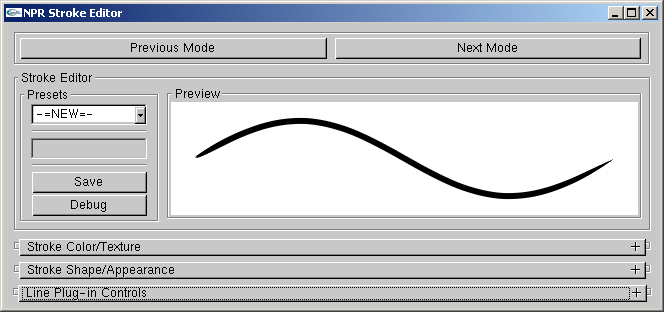
Presets Management.
- Presets
List box for selecting amongst the available presets.
- Save
If "-=NEW=-" preset is selected, a new preset will be created from the current settings. If an existing preset is selected, it will be overwritten with the current settings.
- Debug
Don't ask...
- Preview
Displays the current active settings. Up to five example strokes can be sketched in this box.
Color and Texture Settings
Parameters which govern the rendering of the stroke triangle strip.
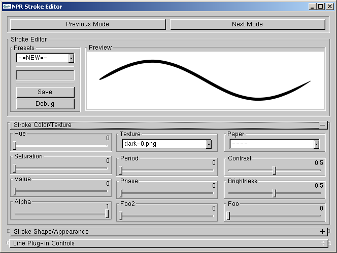
Color and Texture Settings.
- Hue, Saturation, Value
Set the stroke color.
- Alpha
Set the stroke alpha. This is analogous to pressure wrt paper effect simulation shader.
- Texture
Select an alpha texture. The texture can be applied as a 1D or 2D texture. If 1D then the Y direction is mapped across the width of the stroke. If 2D then the X direction is mapped along the length of the stroke.
- Period
If ZERO then texture considered 1D. If NON_ZERO then the texture is considered 2D with period equal to NON_ZERO pixel length.
- Phase
Phase offset (as a fraction of period length) applied to stroke parameterization (i.e. longitude in texture coordinates or sketched offset parameterization).
- Paper
Paper height field texture for paper simulation shader (n.b. strokes do not use the globally selected paper texture).
- Contrast, Brightness
Modify the paper height field texture.
Shape and Appearance
These controls influence mainly the shape of the stroke.
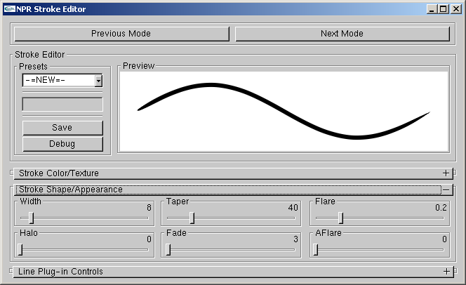
Shape and Appearance.
- Width
Pixel width of the stroke.
- Halo
Don't ask...
- Taper
Distance in pixels over which the end points are tapered.
- Fade
Distance in pixels over which the end points are faded using alpha.
- Flare
Fraction of the stroke over which the width is tapered from one end.
- AFlare
Fraction of the stroke over which the width is faded from one end.
Line Mode Specific Controls
These remaining controls are specific to the line mode.
Line Type Settings
These flags control which line types are rendered for the selected mesh. Silhouette (SIL), backfacing silhouette (BAK), border (BOR), and crease (CRE) line types can be optionally rendered. The visible (VIS), hidden (HID), and occluded (OCC) portions of each line type can be toggled for rendering separately.
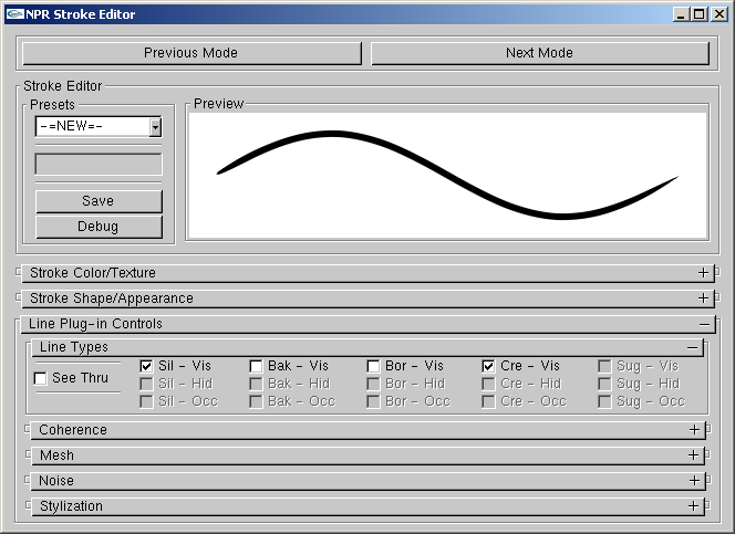
Line Type Settings.
- See Thru
"See thru" objects can render hidden and occluded line types. Non "see thru" objects can render only visible types. Non "see thru" objects can cause hidden lines on "see thru" objects to become occluded lines.
- Sil-Vis, Bak-Vis, Bor-Vis, Cre-Vis
Toggle rendering of the visible line types.
- Sil-Hid, Bak-Hid, Bor-Hid, Cre-Hid
Toggle rendering of the hidden line types.
- Sil-Occ, Bak-Occ, Bor-Occ, Cre-Occ
Toggle rendering of the occluded line types.
Coherence Settings
Settings which govern how a coherent parameterization is applied to each line type from frame to frame (see corresponding paper).
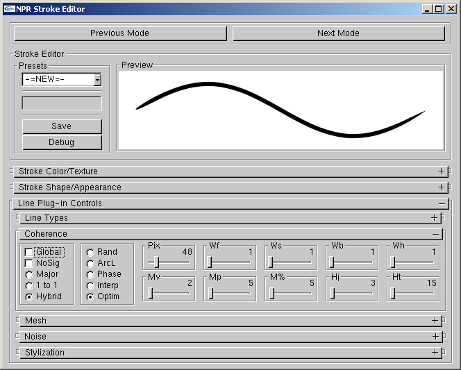
Coherence Settings.
- Global
If checked, all other parameters in this section are ignored and the global defaults are used.
- NoSig
If checked, the onscreen mesh size doesn't influence parameterization (i.e. sigma, rho = 1)
- Major, 1 to 1, Hybrid
Policy for assigning brush paths.
- Rand, ArcL, Phase, Interp, Optim
Policy for fitting parameterization to brush paths.
- Pix
Pixel spacing of polylines vertices for optimization fitting policy.
- Wf, Ws, Wb, Wh
Weights in energy expression for optimization fitting policy.
- Mv
Minimum number of votes per vote group.
- Mp
Minimum pixel length per vote group.
- M%
Minimum percentage of the lenght of the silhouette path per vote group.
- Hj
Pixel length threshold for healing together brush paths.
- Ht
Pixel length threshold for coercing brush paths to heal.
Mesh Settings
Various meshwide settings.
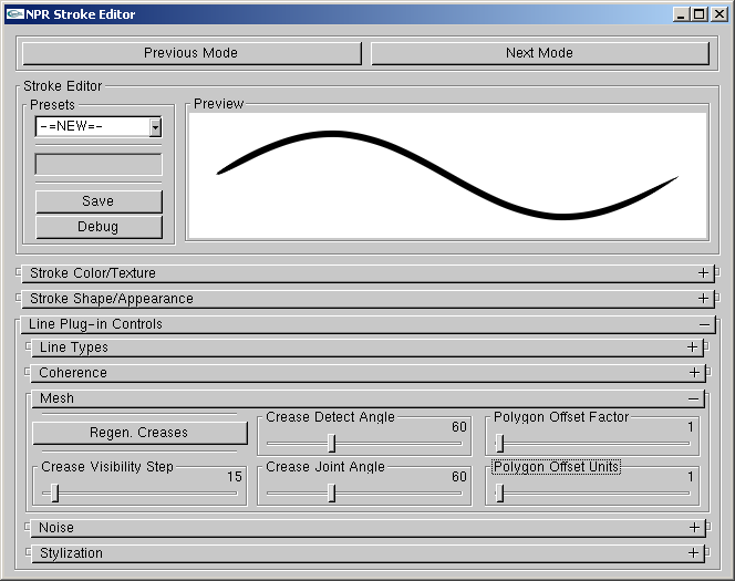
Mesh Settings.
- Crease Detect Angle
Dihedral angle threshold for considering a mesh edge to be a crease.
- Regen. Creases
Regenerates the mesh creases using the current Crease Detect Angle threshold.
- Crease Joint Angle
Adjacent crease edge joint angle threshold for connecting creases in contiguous paths.
- Crease Visibility Step
Pixel spacing of crease visibility testing under legacy crease rendering mode (don't ask...).
- Polygon Offset Factor, Polygon Offset Units
Polygon offset parameters used to render mesh in ID image. Increase these values if line visibility is lousy.
Noise Settings
Line stylization noise (a.k.a. animation of stroke stylization) is achieved by assigning more than one stylization to a given line type and changing among them in time. Note, all additional stylization prototypes for a given line type must share the period (or sketched offset baseline length) of the first prototype.
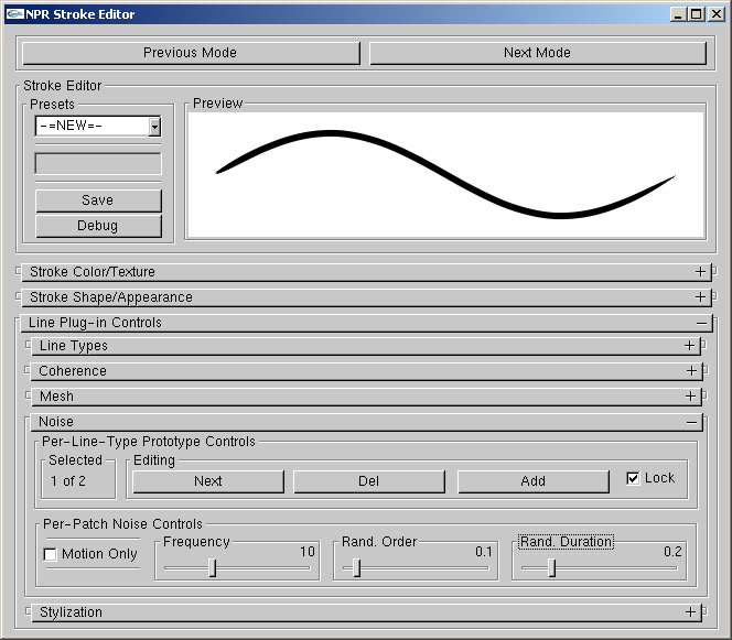
Noise Settings.
- Selected
Indicate which stylization prototype is selected.
- Next
Changes to the next stylization prototype.
- Del
Delete current prototype.
- Add
Add new prototype.
- Lock
Force rendering to lock to current prototype.
- Motion Only
Animation only occurs when camera is in motion.
- Frequency
Number of times per second that the prototype is cycled.
- Rand. Order
Degree to which the prototype cycling order is randomized.
- Rand. Duration
Degree to which the prototype cycling duration is randomized.
Stylization Controls
These controls govern the selection, adding, removal, and editing of stroke stylization for lines types.
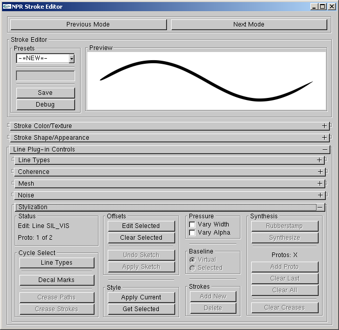
Stylization Controls.
- Status
This field indicates the currently selected entity.
- Line Types
Cycle selection between the line types (e.g. SIL-VIS, CRE-HID).
- Decal Marks
Enter decal editing mode and cycle selection of existing decals.
- Crease Paths
Cycle selection of legacy style crease paths (don't ask...).
- Crease Strokes
Don't ask...
- Edit Selected (h)
Edit the sketched offset stylization of selected line types.
- Clear Selected
Clear the sketched offset stylization of selected line types, or clear the selected decal.
- Undo Sketch (Esc)
Remove the last mark from the current set of sketched offsets.
- Apply Sketch (y)
Apply the current set of sketched offsets to the chosen line type, or generate decals.
- Apply Current (u)
Apply the current stroke parameters (as seen in the Preview window) to the currently selected entity.
- Get Selected (j)
Replace the current stroke parameters (as seen in the Preview window) with those of the currently selected entity.
- Vary Width, Vary Alpha
Toggle effects caused by tablet pressure.
- Virtual Baseline, Selected Baseline
Type of baseline for sketched offsets.
- Add New, Delete
Add and remove legacy style crease strokes (don't ask...).
- Synthesis
Stylization synthesis for legacy style crease strokes (don't ask...).